

Motor Current Signature Analysis
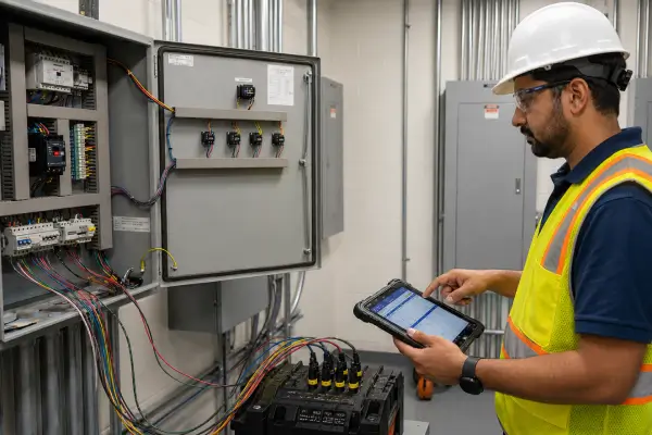
MCSA Portable delivers fast and accurate motor health diagnostics directly at your fingertips without the need for permanent installation. Using advanced Motor Current Signature Analysis (MCSA) technology, the portable system quickly evaluates motor performance, electrical condition, and mechanical health anytime and anywhere.
Designed for on-site inspections and predictive maintenance, MCSA Portable helps detect faults at an early stage, preventing unexpected equipment failures, reducing downtime, and improving overall operational reliability. Its portable and non-intrusive design makes it an ideal solution for industrial motors, pumps, compressors, fans, and other rotating machinery.
The motor current waveform carries valuable fault signatures, where mechanical and electrical anomalies create detectable sidebands, harmonics, and signal modulations. Advanced MCSA technology analyzes these patterns for early fault detection, improved reliability, and reduced downtime.
Current as a Carrier
Motor stator current is the direct output of the electromagnetic process. Rotor, bearing, and load-side anomalies all modulate this signal.
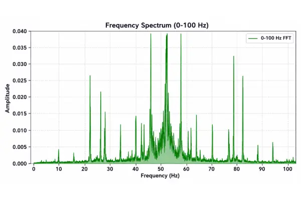
FFT Spectral Decomposition
High-resolution FFT converts raw current into a frequency spectrum, revealing fault signatures as predictable sideband patterns.
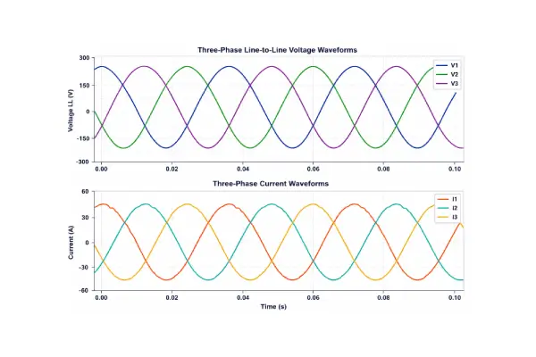
Slip & Speed Estimation
The voltage channel provides precise supply frequency. This allows for accurate motor slip calculation without needing a tachometer.
Power Factor & Impedance
By measuring V and I on the same phase, we compute real-time power factor and load index to detect efficiency degradation.
In a balanced 3-phase motor, a single current phase contains the same core fault information as all three phases. Single-phase ESA accurately detects rotor, bearing, and mechanical faults, while the added voltage channel enables advanced power quality and electrical diagnostics beyond traditional MCSA.
Every fault type generates a unique and mathematically predictable spectral signature within the motor current signal. Advanced MCSA technology continuously monitors these frequency patterns against established severity thresholds for accurate fault detection, early warning, and reliable predictive maintenance.
Rotor
Dynamic Eccentricity
A rotating air-gap asymmetry creates sideband clusters around rotor slot harmonics in the current spectrum, with amplitude proportional to the degree of eccentricity.
Broken Rotor Bar
Asymmetric rotor resistance modulates air-gap flux, generating characteristic sidebands around the supply frequency and its odd harmonics in the current spectrum.
Static Eccentricity
A fixed-position air-gap non-uniformity modulates the supply fundamental and introduces even harmonic distortion detectable in the current total harmonic distortion.
Stator
Stator Inter-Turn Short
Shorted turns create an asymmetric winding that increases harmonic content — particularly 3rd and 5th harmonics — and raises the overall current THD beyond baseline.
Bearing
Inner Race & Ball Fault
Inner race and ball spin frequencies generate amplitude-modulated sidebands around supply harmonics, with modulation depth increasing as the bearing defect progresses.
Outer Race Fault
The ball pass frequency (outer race) modulates motor current via air-gap variation and torque ripple, producing sidebands around supply frequency multiples at incipient stage.
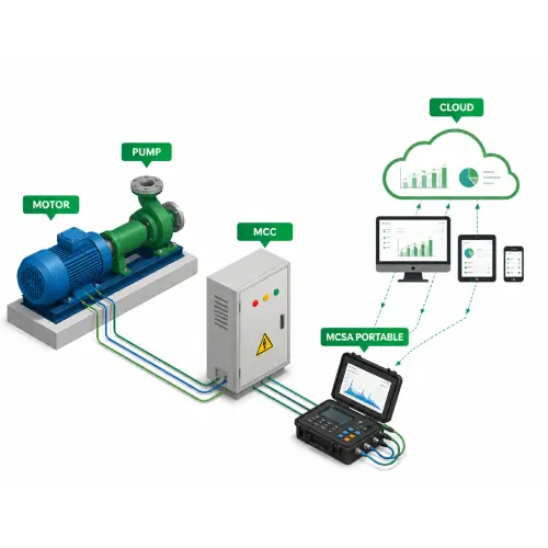
Advanced online motor and drivetrain condition monitoring enables continuous detection of six major fault categories without interrupting production or machine operation. Using Motor Current Signature Analysis (MCSA) and Electrical Signature Analysis (ESA), the system accurately identifies electrical and mechanical abnormalities in real time.
Monitor Scope
All detectable faults are analyzed using a single phase of voltage and current, eliminating the need for additional sensors on the motor shaft, bearings, or machine frame. The non-intrusive monitoring approach utilizes existing electrical panel connections, making installation simple, safe, and highly efficient for predictive maintenance applications.
Rotor
Broken / Cracked Rotor Bars
MCSA sideband detection. Severity proportional to sideband amplitude relative to fundamental.
End-Ring Fracture
Similar spectral signature to broken bars with additional torque ripple modulation.
Dynamic Eccentricity
Rotating air-gap imbalance — sidebands around rotor slot harmonics.
Static Eccentricity
Fixed-position air-gap asymmetry — detected via supply harmonic distortion.
Mixed Eccentricity
Static + dynamic combination; distinguishable via harmonic ratio analysis.
Stator
Inter-Turn Short (Monitored Phase)
Shorted turns increase 3rd and 5th harmonics and raise current THD.
Winding Insulation Degradation
Tracked via increasing harmonic distortion trend and load-normalized current deviation.
Coil-to-Coil Short
Identifiable via current asymmetry index relative to baseline.
Power
Supply Voltage Harmonics (THDv)
5th, 7th, 11th, 13th harmonic distortion measured per phase from three voltage channels.
Supply Frequency Deviation
Grid frequency drift detected in real time — affects speed, efficiency, and sideband calculations.
VFD / Inverter-Induced Harmonics
PWM carrier and inter-harmonics isolated to prevent false fault triggers.
Power Factor Degradation
Real-time PF tracking — early indicator of winding degradation.
Motor Efficiency Decline
Efficiency index from V, I, PF — trending reveals progressive deterioration.
Voltage Sag / Swell Events
Short-duration voltage anomalies captured and time-stamped.
High Impedance / Connection Fault
Loose terminals and cable degradation detected via current harmonic variation.
Bearing
Outer Race Defect (DE / NDE)
BPFO sidebands around supply frequency. Detectable at incipient stage.
Inner Race Defect
BPFI sidebands with amplitude modulation at rotational frequency.
Rolling Element (Ball) Defect
BSF sidebands with cage frequency modulation detectable via current spectrum.
Lubrication Degradation
Elevated broadband noise floor and rising bearing frequency amplitudes over time.
Mechanical
Shaft / Coupling Misalignment
1× and 2× running speed sidebands via torque modulation in current spectrum.
Mass Imbalance (Rotor / Fan / Impeller)
1× rotational frequency peak. Increases with speed squared; unambiguous frequency.
Mechanical Looseness
Sub-harmonic components (0.5×, 1.5×, 2.5× running speed) plus broadband noise.
Gear Mesh Faults (Gearbox)
Gear mesh frequency and sidebands detectable via load torque modulation.
Broken / Chipped Gear Tooth
Impulsive torque at GMF with sidebands. Detectable even in inaccessible gearboxes.
Coupling Wear / Belt Tension Fault
Belt defects at belt pass frequency; coupling wear elevates 2× and 3× components.
Load
Pump Cavitation
High-frequency broadband noise and blade pass frequency modulation in current.
Fan Blade Pass Anomaly
Damaged blades modulate current at blade pass frequency and sub-harmonics.
Cyclic / Pulsating Load Torque
Torque-driven sidebands at load cycle frequency — compressors, piston pumps.
Motor Overloading
Detected via load index (I_rms vs rated) and power factor trend.
Motor Underloading / No-Load Running
Load index below threshold indicates process-side fault — blocked inlet, broken impeller.
Phase Voltage Unbalance
Requires all three voltage measurements. Cannot compute IEC / NEMA unbalance percentage from single phase.
Phase Current Unbalance Quantification
NEMA current unbalance ratio requires all three current channels simultaneously.
Negative Sequence Component Analysis
Symmetrical component decomposition requires all three phase voltages and currents.
Single-Phasing (Loss of One Phase)
Cannot detect loss of an unmonitored phase. Full 3-phase monitoring required for reliable alarm.
Phase-to-Phase Fault Localisation
Identifying which phase pair has a fault requires individual current measurement per phase.
Stator Fault in Unmonitored Phases
Inter-turn short in Phase 2 or 3 insufficient resolution in Phase 1 at early stage.
True 3-Phase Active Power (kW)
True 3-phase power requires V and I on all three phases. Single-phase estimate assumes balance.
NEMA / IEC Derating Factor
NEMA MG1 derating requires all three voltages to compute the voltage unbalance ratio.
Phase Rotation / Sequence Fault
Reversed phase sequence detection requires all three phase angle relationships.
Zero-Sequence Ground Fault Detection
Residual current measurement requires summing all three phase currents — not possible with single CT.
Full diagnostic capability comparison. ✓ Full ◐ Partial/inferred ✕ Not available.
| Diagnostic Capability | MCSA Portable (2 Channels) | MCSA Online (8 Channels) | Notes |
| Broken Rotor Bar Detection | ✓ Full | ✓ Full | Identical — fault appears in all phases equally |
| Air Gap Eccentricity (Dynamic & Static) | ✓ Full | ✓ Full | Fully resolved from single-phase current spectrum |
| Bearing Outer / Inner Race Faults | ✓ Full | ✓ Full | Equivalent sensitivity; both rely on MCSA |
| Shaft Misalignment & Imbalance | ✓ Full | ✓ Full | Mechanical sidebands appear in all three phases |
| Gearbox Fault (GMF Analysis) | ✓ Full | ✓ Full | Torque modulation appears uniformly across phases |
| Stator Inter-Turn Fault (Monitored Phase) | ✓ Full | ✓ Full | Single-phase covers monitored winding completely |
| Stator Fault — Phase Isolation | ◐ Partial | ✓ Full | 8C localises fault to specific phase A, B, or C |
| Phase Voltage Unbalance | ✕ No | ✓ Full | Requires all three voltage inputs |
| Phase Current Unbalance | ✕ No | ✓ Full | Requires all three current inputs |
| Negative Sequence Component | ✕ No | ✓ Full | Symmetrical component analysis needs 3-phase data |
| Single-Phasing Detection (Any Phase) | ◐ Partial | ✓ Full | 2C detects only if monitored phase is affected |
| Zero-Sequence Ground Fault | ✕ No | ✓ Full | Requires summing all three currents for residual |
| Phase Rotation / Sequence Error | ✕ No | ✓ Full | Phase angle between all three phases must be measured |
| Supply Voltage THD (Per Phase) | ◐ Phase 1 only | ✓ Full (1+2+3) | 8C measures THD independently on all three phases |
| True 3-Phase Active Power (kW) | ◐ Estimated | ✓ Full | 2C assumes balance; 8C computes from all 6 channels |
| Power Factor (Per Phase) | ◐ Phase 1 only | ✓ Full (1+2+3) | 8C computes per-phase PF and total |
| Motor Load Index | ✓ Full | ✓ Full | 8C uses true 3-phase load index; more accurate |
| VFD Harmonic Isolation | ✓ Full | ✓ Full | PWM carrier resolved; 8C cross-validates across phases |
| NEMA Derating Recommendation | ✕ No | ✓ Full | NEMA MG1 derating requires 3-phase voltage unbalance |
Professional-grade ESA where 3-phase monitoring is cost-prohibitive, access-restricted, or simply unnecessary.
Wind Turbines
Generator, main bearing, gearbox, and drivetrain detection from the generator terminal. No nacelle access required.
Pump Systems
Cavitation, impeller wear, bearing faults detected from the MCC panel — ideal for submersible or inaccessible pumps.
Compressors
Valve faults, piston wear, and cyclic load anomalies captured via current — no intrusive sensors needed.
Conveyor Drives
Gearbox tooth wear, belt tension faults, and bearing degradation across drive motors in mining.
Critical Process Motors
Any motor where vibration sensor installation is restricted — ESA provides equivalent or superior early fault detection.
MCC / Panel Retrofit
Permanently installed at the motor control centre. No motor modification — connects to existing panel taps.
Fleet Monitoring
Low per-motor cost enables deployment across large motor fleets — condition-based vs time-based maintenance.
Hazardous / Remote Areas
Device located remotely in a safe zone monitoring motors in Ex-rated environments — no proximity needed.
Full diagnostic capability comparison. Hardware specifications for panel installation and integration with existing monitoring infrastructure.
| Specification | Value | Details |
| Power Supply | 5V DC | via terminal connection |
| Communications | Ethernet 10/100 Mbps | Modbus TCP · REST API |
| Input Channels | 2 Channels | 1× Voltage (V) 1× Current (I) |
| Voltage Input | Up to 800V AC | Direct input or PT secondary |
| Current Input | CT Secondary | 1A max (configurable) |
| Sampling Freq. | 10 – 20 kHz selectable | Simultaneous both channels |
| Supply Frequency | 50 / 60 Hz | Auto-detected from voltage channel |
| Installation | DIN Rail 35mm | Panel or JB mounting |
| Dimensions | Compact DIN form factor | Low profile panel footprint |
Bearing failure
Stator winding failure
Power Loss Analysis
Interturn faults
Phase-to-phase faults
Broken/cracked rotor bars
Static and dynamic rotor eccentricity
Phase Imbalance
Rotor shaft misalignment
Mechanical Imbalance Degraded
Pump, Gearbox, Belt Pulley,
Blower Fan, Faults
Instant report with fault diagnosis
ISO 20958 CM report
Short test time (5minutes)
Advance time waveform analysis
Advance frequency spectrum analysis
Early failure detection
Detects motor faults and load anomalies early
Reduces unplanned downtime and production loss
Potential energy savings